Audio Engineering Techniques :

As mentioned in my “About Me” page, is that I prefer the recording process, rather than being a performer. Personally, such is more rewarding to create something of a positively enduring nature—ultimately, having gained a sense of pride in achievement. In a relative sense, the following info provided will essentially explain my audio engineering techniques.
NOTE : To prevent malfunction and/ or damage to speakers or other devices, always turn down the volume, and turn off the power on all devices before making any connections—as below :
Pre-Amplifier :
Step # 1 : After I setup my guitar-based TONES for the recording stage (guitar > effects pedals > “amplifier”), I then choose what type of recording pre-amplifier that will enhance the overall sound. A preamp is provided as a built-in feature of a mixing console, computer audio interface, stand-alone digital recording device, or in the form of an individual processing unit—designed to be employed as an outboard (separate) module. Moreover, an outboard pre-amplifier is intended to be patched into a particular connection point (if provided) of a mixing console called, a channel insert. Ultimately, such will thus “bypass” the mixer’s inherent preamp channel, in favor of the outboard unit.
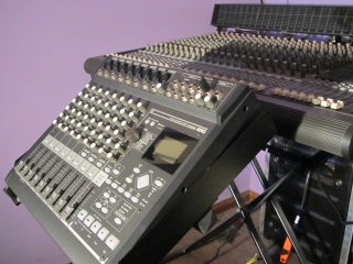
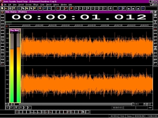
That said, I will initially, record thru a pair of analog solid-state preamps (which, are a built-in feature of my mixing console), so as to record a stereo musical instrument track into a digital audio recorder (i.e., preamp > computer audio interface > DAW/ digital audio workstation software application). In this manner, a digitized .wav audio file is created (@16-bit resolution/ 44.1 kHz sample rate). If the preamps that you choose to employ are a built-in feature of a mixing console, then first, raise their relative channel faders to unity gain level (U/ +0 dB). Likewise, do the same employing the console’s stereo master fader. Such will ensure that your audio will be recorded with a proper signal-to-noise ratio. Otherwise, volume decrease beyond (less than) -10 dB reduces bit-depth (i.e., 24-bits to 20-bits).
Each pre-amplifier channel provides a feature for controlling panorama/ pan adjustments (for details, please read Step # 6 as provided below). That said, assign “channel # 1” as the left-side of the stereo image. Next, set its relative pan control fully-counterclockwise (left). Likewise, assign “channel # 2” as the right-side of the stereo spectrum, and setting its relative pan control fully-clockwise (right).
The stereo pair of pre-amplifiers that I employ also, sport trim controls. This particular preamp feature provides fine-tuning adjustment, in which to help create a full-bodied sound. Whenever possible, I personally choose to leave this control set @ minimum level; choosing to instead, increase the initial overall volume (dB) level @ source (i.e., modeled guitar amplifier), until the sound becomes most full, without clipping (distorting) the audio signal. For example, the only distortion I desire to record, is that of my chosen over-driven amplifier and effects pedal TONES—leaving the recording pre-amplifier to remain clean/ linear-voiced. Ultimately, such insures a properly-recorded audio track.
Otherwise . . if increasing the guitar “amplifier” and effects pedal dB levels does not provide enough volume boost, then increase the dB level @ the pre-amplifier’s trim controls (if provided)—one channel @ a time. To do this, initially mute (or, fully-lower the volume level) a single preamp channel; so as to only, listen to (monitor) one side of the stereo image. Next, gradually increase the channel’s relative trim control to slightly clip the signal—just enough to realize the actual clipping point—then, gradually decrease said level to provide a full-bodied, clean/ linear-voiced sound. After achieving the intended result, do the same with the second channel—remember to leave one channel muted, whilst monitoring (listening to) the other.
When both channels are properly set to provide a clean full-frequency sound, then UN-mute both preamp channels to monitor said results. From there (listening in stereo mode) you can thus, further experiment via their relative trim controls to fine-tune the overall balance of the stereo-field. Again . . just remember, to avoid clipping the pre-amplifier’s audio signal.
Apply outboard pre-amplification to an entire sound mix of recorded musical instruments :
Step # 2 (optional) :
A.) Prepare to playback (and monitor) the mix from the sound recorder, whilst recording from a secondary source (i.e., playback device > outboard pre-amplifier > recording device).
NOTE : @ all times, choose to monitor your sound mix @ a low volume level, employing pro-grade headphones (i.e., Sony MDR-7506). In this manner, your finished results will “bloom” with energy thru loudspeakers @ any volume level, there afterward. Otherwise . . if you monitor @ high dB levels, your mix will have the opposite effect—sounding small, along with an overall weak bass frequency.
B.) Patch the stereo output of the playback device into a pair of input channels (pre-amplifiers) @ the mixing console.
C.) Prepare both input channels to receive audio signal, as previously described in Step # 1 (NOT Step “A”).
D.) Patch the output of a stereo tube/ valve (or solid-state) preamp into a pair of insert points @ the mixing console, relative your selected input channels. Employ proper insert cables to make this connection.
NOTE : If the mixing console does not provide insert connections, then opt for a pair of input channels, instead (i.e., patch the stereo output of the playback device into the stereo outboard preamp, subsequently patching the stereo output of the outboard module into a pair of input channels @ the mixing console).
E.) Lower the volume and gain levels of the inserted preamp to minimum.
F.) Playback and monitor the music mix from source, whilst setting the initial volume (dB) level from the source unit, itself—in this manner, the overall dB of your mix will thus be controllable via the playback device. Begin @ minimum dB, then increase its level, that which is comfortable and safe (i.e., not loud). Moreover, you can always re-adjust the overall volume via this particular control feature; thus, helping to maintain a clean/ linear audio signal—free of unwanted distortion.
G.) @ this point in the procedure, switch-over monitoring from the source unit, and monitor from the mixing console as the audio signal is being played back. Gradually increase ONLY the volume level (not the gain level) from ONE of the inserted preamp’s stereo channels, until the audio signal begins to sound slightly distorted.
H.) Whilst monitoring the playback audio, gradually decrease the dB level of channel # 1, until you arrive @ a clean/ linear sound.
I.) Repeat Step “H”, employing channel # 2 of the inserted stereo preamp (if possible, mute channel # 1).
J.) In stereo mode (both preamp channels engaged), slightly re-adjust the volume levels (if necessary) to achieve a balanced sound.
K.) Slightly re-adjust the playback volume level from the sound source (if necessary).
L.) Slightly re-adjust the master fader volume level @ the mixing console (if necessary).
M.) @ this point of the procedure, switch-over monitoring from the mixing console to the audio recording device (NOT the playback device). In this manner, you will have the best perspective of how your mix will sound, prior to having recorded the final result @ +0 dB (or, slightly below that mark for a less intense sound; though, no greater than -10 dB). If necessary, re-check Steps K and L.
NOTE : Ultimately . . sound process an entire mix of recorded musical instruments, without adding unwanted distortion. As result, having simultaneously provided greater dimension, detail, and warmth.
NOTE : If your mixing console provides additional insert connection points (as a main stereo insert, as oppose to channel inserts), you can then add sound processing via a second outboard module as well (i.e., compressor/ limiter). Employ proper insert cables to make this connection. But FIRST, follow Steps A thru M to apply outboard pre-amplification to a sound mix.
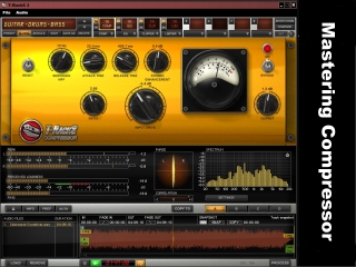
Compressor :
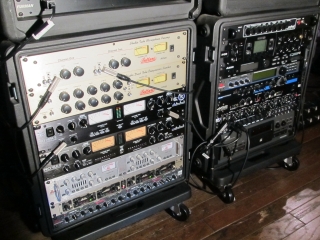
Step # 3 : After having created a balance of dB level (Step # 1), I subsequently, employ an outboard sound processing unit designed to compress my sound mix of musical instruments. Essentially, the function of a compressor is to help further balance the overall dB level. For example, depending upon how well you set its controls (with practice), such will then force your mix to maintain a steady dB level—not too loud, not too quiet. In other words . . the most quiet and loudest sounds will be equal to one another in volume level—thus, having created an improved balance. In this manner, your sound mix will be nearer to that of a professional “polished” result (and producing a desirably soft/ smooth overall character as well).
A compressor (or, limiter) may be provided as a built-in feature of either, a mixing console, DAW (digital audio workstation) software application, stand-alone recording device, or in the form of an individual processing unit—designed to be employed as an outboard (separate) module. For example, an outboard unit is intended to be patched into a particular connection point (if provided) of a mixing console called, a channel insert. Alternatively . . such can be patched into the main stereo insert point; thus, leaving room to also include an additional outboard processor to be patched into said channel insert—such as a stereo preamp, equalizer, or similar device.
NOTE : Depending upon personal preference, you can either over-compress audio with intent to create a powerful illusion of volume (dB) increase, or that of a subtle effect. Just remember . . NOT to excessively over-compress; otherwise, the audio signal will sound harsh. Ideally . . musical, gently-compressed audio is the intended goal; because, when a sound mix is ready for the master engineering stage (as mentioned below/ Step # 9), such will yet be further compressed for a final measure of sonic “polishing”—and that is where a “larger-than-life” illusion is thus achieved.
Limiter :
Step # 4 (optional) : A limiting device is designed to limit the intensity of an audio signal, so that sound will not exceed unity gain level (+0 dB). In other words, an increase in digitized volume level beyond +0 dB will thus produce undesirable distortion (clipping). Generally, there are 2 different applications for employing the limiting process :
- Reduce an excessively loud sound, so as to avoid a distorted signal. For example, limiting the sounds—during the recording process—of strummed acoustic guitars, a slapped bass guitar technique, and “crashing” drum cymbals.
- Increase the level of sound just below unity gain (+0 dB), so as to create a powerful illusion of loudness. For example, most radio stations will employ a limiter in this manner, so that their audio signal will stand-out prominently. That said, if your music is intended for radio broadcast, you may not need to apply the limiting process beforehand. As result, your mix will actually sound better; ultimately, not being overly processed.
Note : Music of the Classical genre is traditionally without the need for audio compression and/ or limiting, so as to retain the sonic integrity of its natural dynamic range. In other words, keeping a musical instrument’s original highest and lowest volume levels to remain intact.
Equalizer/ EQ :
Step # 5 : The purpose of an equalizer is to decrease (cut), or increase (boost) a particular audio frequency. For example, if a recorded musical instrument sounds as though it is lacking in treble, mid-range, and/ or bass frequencies, then such can be corrected by increasing said frequency level(s). Relatively, if any frequencies of a recorded audio track sound too intense, then such can be corrected by decreasing said frequency level(s)—ultimately, better-providing a well-balanced mix of sound.
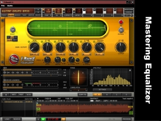
An equalizer (EQ) may be provided as a built-in feature of either, a mixing console, DAW software application (as pictured, right), stand-alone digital recording device, or in the form of an individual processing unit—designed to be employed as an outboard (separate) module. Moreover, an outboard module is intended to be patched into a particular connection point (if provided) of a mixing console called, a channel insert. This procedure will “bypass” a mixer’s inherent equalizer section, in favor of the outboard unit—provided that the mixer’s equalizer controls are either, set flat (no EQ added), or that the equalizer section provides a bypass feature in which to turn off the mixer’s built-in EQ. Ultimately . . achieving well-balanced equalization, will thus help to create an overall “polished” (professional) result.
Panorama/ Pan :
Step # 6 : A pan adjustment control is generally available @ the mixer’s channel section—usually, located somewhere above each fader dB control (likewise, as part of a DAW software mixer as well). This feature is intended to adjust where a particular audio track is heard within the left-right stereo spectrum of a mix. In other words, avoid having each recorded musical instrument placed in the same location within the stereo-field. For example, each instrument can thus be placed further to the left or right of one another; ultimately, having created their separate space to be better heard.
Stereo-Width :
Step # 7 (optional) : Widening the stereo image is similar to the aforementioned panorama adjustment (Step # 6). The difference is that such is intended for the entire sound mix, as oppose to that of an individual audio track. This sound process must be adjusted in a subtle manner, otherwise the overall mix will become soft and weak—as well as sounding unnatural. An alternative term for stereo-width is called, a “stereo spread”.
Personally, I employ this particular sound process via 2 different audio mastering software applications : T-Racks (by IK Multimedia), and Audio Cleaning Lab (by Magix). I assume, that such is also available as part of many other DAW software applications as well? Similarly . . if a hardware version does exist? (i.e., TC Electronic Finalizer Plus/ 96K), then my guess is a stereo enhancement sound process may be part of the unit’s features. That said, if a hardware version is to be employed, then it is best connected into a mixing console’s main (stereo) insert point—as oppose to individual channel insert points (if provided).
Echo/ Delay :
Step # 8 (optional) : Echo and delay are NOT quite the same definition; though, both terms describe the illusion of a sound heard (for example) from within a canyon—such, bouncing/ reflecting off of canyon walls. Echo thus, creates the illusion of your sound to be heard less-intensely (fewer milliseconds of time) as that of delay. In other words . . delayed effects have a longer time to arrive back into your ears; ultimately, creating a deeper and larger illusion of sound space. Good practice in achieving said results, is to employ a subtle amount of either effect of choice to a sound source—whether such be that of an individual audio track, or an entire sound mix. I personally, prefer to add delay/ echo ONLY to that of the electric guitar sound via an effects pedal patched into the fx loop of my Line 6 guitar “amplifier”. In this manner, the delay/ echo effect will remain clean/ linear-voiced, and thus independent of/ unaffected by any intentional distortion arriving from the “amp”.
Similar . . by nature, is that of the reverberation effect; which is also time-based. The essential difference, is that such is the illusion of sound reflecting off of a room space (i.e., small room, large concert hall, or anything in between).
These types of sound process’ may be provided as a built-in feature of either, a mixing console, DAW software application, stand-alone digital recording device, or in the form of an individual processing unit—designed to be employed as an outboard (separate) hardware module. Moreover, an outboard processor of this nature is intended to be patched into particular connection points (if provided) of a mixing console, which is called an effects send/ return.
Master Engineering :
Step # 9 : One could understand this particular step of the sound engineering process, as that of a final sonic “polish”; fine-tuning many of the adjustments and levels as previously mentioned, herein. For example, importing a mix-engineered .wav audio file (16-bit resolution/ 44.1 kHz sample rate) into a special DAW software application designed for master-engineering purposes—ultimately . . employing additional compression, equalization, stereo-width adjustment, as well as an increase of dB level.
Sound processing designed for traditional mastering applications has a “transparent/ invisible” quality to its elusive nature. In other words . . when applied properly in a subtle manner, sonic results thus appear as “larger-than-life” and “magical”. In a relative sense, the same type of application can be that of a vintage nature—for example . . vintage-modeling, vintage-inspired analog, or actual vintage analog technologies. I personally, employ the vintage type : modeled tube/ valve sound processors by IK Multimedia (i.e., standard T-Racks compression and equalization).
Master Recording Level : After having processed the sound mix (incl. that, of the master engineering stage), it is the digitized master-engineered volume (dB) level which is the final step—in terms of setting said, overall level. Ultimately, the final dB must be set to unity gain (+0 dB). Going past this mark will incur undesirable distortion (clipping), which is therefore termed as an “over” (over +0 dB). For example, audio on a CD/ compact disc which has been recorded beyond +0 dB will not play back well—and possibly, not at all. Incidentally, my personal preference is to process audio files just under +0 dB, prior to the mastering stage (i.e., no greater than -10 dB). The reason for this, is that the overall dB level sounds less intense, and more musical. Though, volume decrease beyond -10 dB reduces bit-depth (i.e., 24-bits to 20-bits). That said, I personally, set the final dB level via the two aforementioned sound processors : IK Multimedia T-Racks Compressor and Equalizer.
NOTE : It is not always necessary to achieve an overly-loud illusion of dB increase. For example, when setting dB levels, listen to how the volume effects the overall musical TONE and energy of the mix—which may sound better @ a lower level. Ultimately, such is a matter of personal preference.
Audio Conversion/ File Compression :
Step # 10 : After having created a master-engineered .wav audio file (@ 16-bit resolution/ 44.1 kHz sample rate), I then subsequently, convert said file into either of the following formats : .mp3, or .wma. (128 Kbps @ CD-quality). My personal preference of the 2 compressed audio file formats (as of yet) is specifically, .wma7. Incidentally, to my ears, the audio fidelity of .wma7 is smoother sounding and less intense—I even prefer such to that of the original master-engineered .wav file. Ultimately . . I employ file compression, so as to create a manageable file size intended for Internet purposes (i.e., 30 MB converted to 3 MB).
NOTE : I save both file types . . one for video production (either, .mp3 or .wma7), and one for archival purposes (.wav). Incidentally, the vintage software application which I employ to convert/ compress said audio, is that of Vegas Video by Sonic Foundry.
Epilogue :
I hope that what I’ve provided as an essential overview of my personal recording techniques, has helped inspire you to craft your own unique sound mixes. To the average home studio enthusiast, what’s been mentioned herein, must seem rather involved. As you realize by reading this post, such is NOT merely twiddling knobs on effects pedals. Rather . . such is to show how effects pedals enhance music recordings, along with pro-audio gear.
This Website :
The intention of fuzz-effect-sounds-and-more.com is to provide a reference resource; virtually sharing my gear collection, so that readers are made greater-aware of particularly good-sounding (and, in some instances), potentially collectible effects pedals. Otherwise, to also help those whom might benefit from my recording/ engineering techniques. Ultimately, as I continue to build and design this site, I will gradually introduce additional collection-based content—such as blog posts, image galleries, audio, video, and official manufacturer web links for your convenience. The information provided herein, is based upon biased opinion. Please, do your own research.
Ebooks :
Later . . I will offer for sale Part 1 of a series of self-authored eBooks, in relation to fuzz effects pedals; subsequently, also offering additional volumes regarding other effects types—boost, overdrive, distortion, etc—all via my private, independent collection. Moreover, these tomes of tone will include audio examples, color images, (in most cases) close-up circuit views, and generalized spec. information. Otherwise, said eBooks regarding fuzz effects pedals will additionally incl. generalized historical information as well. For details, please read this site’s eBook advertisement page.
THANK YOU for your interest of fuzz-effect-sounds-and-more.com
– Michael.
![]()
Disclaimer of Copyright & Trademark :
Product names, trademarks, and artists’ names (incl. the names of builders and designers) referred to, and/ or depicted herein are the property of their respective owners, which are in NO way associated or affiliated with fuzz-effect-sounds-and-more.com. Said, names and trademarks are used solely to identify products whose sounds were studied during the audio production efforts for this reference resource. The use of said, names and trademarks does NOT imply any cooperation or endorsement. NO copyright, nor trademark infringement intended. Any errors, omissions or variations in the subject-matter details are unintentional.
Disclaimer of External Web Links :
EXTERNAL web links are provided as a convenience, and for informational purposes only; they do NOT constitute an endorsement or an approval by fuzz-effect-sounds-and-more.com of any of the products, services or opinions of the corporation or organization or individual. fuzz-effect-sounds-and-more.com bears NO responsibility for the accuracy, legality or content of the external site or for that of subsequent links. Contact the external site for answers to questions regarding its content.

This Website & Its Contents : Copyright © fuzz-effect-sounds-and-more.com